UN Approved Packaging Explained
United Nations (UN) Approved Packaging is packaging which has been designed, tested and certified to enable the safe transportation of Dangerous Goods via road, sea, rail or air.
Why do we need UN Approved Packaging?
Dangerous goods are articles or substances which are capable of posing a hazard to health, safety of people or animals, property or the environment. UN approved packaging is designed to enable the safe transportation of such dangerous goods. Its intention is to prevent and subsequently contain a leak or exposure should the substance/article or the packaging become compromised during transportation. For example, should a package containing dangerous goods fall from a shelf or wagon, the substance or article inside remains safe or contained within the package.
As well as using UN approved packaging to mitigate risk to people, animals and the environment, it also means with its usage comes the proper declaration of the dangerous goods by the shipper, this ensures that all involved in the transportation chain know exactly what they are transporting, how to handle them and what to do should an incident or accident occur.
What does it look like?
UN approved packaging can come in various forms, materials and sizes. Packaging types include, drums, jerricans, boxes, bags and composite packaging. The packaging material is wide ranging, some examples include, fibreboard, plywood, steel, plastic and aluminium but there are many more.
Generally, UN approved packaging tends be referred to as either combination packaging or single packaging. Combination packaging is basically an UN Approved Outer packaging and within that outer packaging would be the inner receptacles or inner packaging, as well as any absorbent or cushioning material to protect the inner(s) containing the dangerous article or substance. An example of this would be a fibreboard outer box containing glass bottle inners, within the inners would be the dangerous goods. UN Approved Single packaging is packaging that does not require any inner packaging in order to perform their containment function during transport, here an example would be a steel drum directly containing the dangerous goods.


Why is it different from everyday packaging?
Dangerous goods packaging differs considerably to everyday packaging, such as household containers used to store and transport. Higher specification materials are used to create UN approved packaging, the material and the packaging design needs to be robust enough to withstand the knocks and bumps that can occur when in transport, providing extra protection to the contents to limit the likelihood of leakage and potential harm to the external environment. All UN approved packaging are subject to packaging specifications and tests stipulated in the relevant transport regulations to ensure the packaging is capable of withstanding normal conditions of transport.
How do we know it’s fit for purpose?
In order for a package design to become UN Approved the packaging itself has to pass rigorous tests specified in the relevant DG regulations. The manufacturer designing the packaging must adhere to strict guidelines regarding packaging specification and ensure the packaging passes a number of tests to prove it is capable of withstanding normal conditions of transport. The designed package is then sent to an independent testing company, provided that it successfully passes the tests, it is then sent to the relevant state approval authority for verification and approval and then assigned a UN Specification Mark. The package design is now classed as UN Approved and can now be manufactured and sold to consumers with the specific use of transporting dangerous goods.
What is a UN Specification Mark?
A UN specification mark is made up of numbers and letters, directly following a ‘UN’ logo. The example below is of a UN mark that would be displayed on an UN approved fibreboard box – known as a 4G package.
How to read UN markings
The image below breaks down UN identification code for a 4G fibreboard box.


What are Packing Groups?
Packing groups provide an indication to the level of danger the dangerous goods, substance or article poses.
- Packing Group I (X) represents high danger
- Packing Group II (Y) represents medium danger
- Packing Group III (Z) represents low danger
Can I, Can’t I?
It is a legal requirement to package dangerous goods according to the relevant transport regulation, ‘relevant’ meaning if you are transporting your goods via air travel then you must consult International Civil Aviation Organisation (ICAO)/International Air Transport Association (IATA) and adhere to their regulations, however if your goods have arrived at or are collected from the airport on a wagon then you also need to adhere to European Agreement concerning the International Carriage of Dangerous Goods by Road (ADR) as part of the transport journey includes road. Transporting Dangerous Goods can be complicated, there is often misconceptions surrounding less common regulations that often result in hidden, undeclared and incorrectly packaged dangerous goods.
It is the shipper’s responsibility to ensure that the dangerous goods are packaged, marked and labelled correctly in line with the regulations relevant for the mode of transport they are using e.g. ICAO/IATA, ADR, Regulations concerning the International Carriage of Dangerous Goods by Rail (RID) and the International Maritime Dangerous Goods Code (IMDG).
If you require any assistance choosing the right packaging for your dangerous substance or article, get in touch, our trained advisors are here to help.
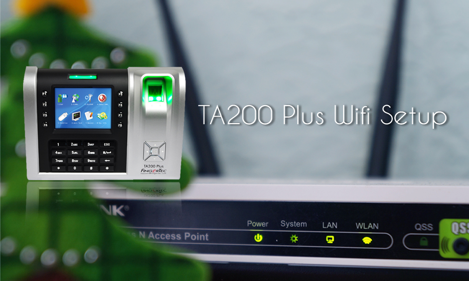
TA 200 Plus Wifi Setup
Process
A — Wi-Fi Setup
1. Check out available wireless within your network range from your device. Go to Menu> Comm. > Wireless LAN. TA200 plus Wi-Fi can only support 2.4 GHz Network band. Therefore, Wi-Fi that uses 5.0 GHz network band will not be visible or connected to the device.
2. Use the navigation key to select your Wi-Fi. Press M key to set up the Wi-Fi.
3. Refer to the table below for the security settings supported by the device. These settings have been set up on the server. Thus, it is advisable to consult an IT person for details on these settings.
4. By default, the keypad is in numeric keypad for you to insert the password. However, you may change it to the alphabet by pressing the * button and press the number according to the alphabet that you need. If your password requires a symbol, press the * button again. If you need more symbols, click on the right button to view other selection. Please bear in mind that space is not an option for the password.
5. IP Address selection will be either in Manual or DHCP. If you select Manual, you need to fill up all the details as shown below. For DHCP, you are not required to manually assign an IP address.
7. In the DHCP setting, the device will take a few minutes to boot up. For Manual setting, the device will boot as usual.
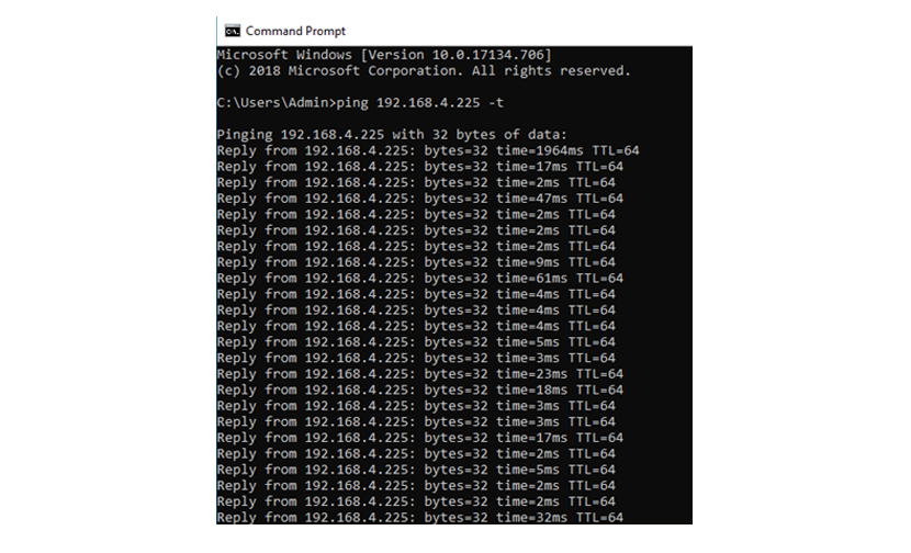
B — Test connection
TA200 plus Wi-Fi does not show any signal bar on the desktop. To test your Wi-Fi, you need to follow the following steps:
1. Connect your PC to the same Wi-Fi network that your device is connected to.
2. Use command prompt to ping device IP address. If the DHCP is set, go to Menu> Comm> Wi-Fi setup. You will see a new IP address for that, already assigned by DHCP. If it shows the IP address not available, please check your Settings.
Here is an example, if you are confused about the Wi-Fi security settings.
1. By using the Pc that is already connected to the targeted Wi-Fi, go to Control Panel> All Control Panel Items> Network and Sharing Center> click connection of connected Wi-Fi network> WIFI status> Wireless Property> security.
Русские Блоги
Сравнение разборки между оригинальным зарядным устройством EP-TA20JBE для Samsung Note8 и оригинальным зарядным устройством EP-TA200 для Samsung Note7
Со времени внутренней конференции Samsung S9 / S9 + прошло более месяца, и сеть Charging Head Network впервые дала вам оценку зарядки Samsung S9. после тестирования,Samsung S9 может достичь быстрой зарядки только 10 Вт с помощью оригинального зарядного устройства,хотяСовместим с протоколом быстрой зарядки USB PD, Но скорость зарядки существенно не улучшилась.
Кроме того, сеть зарядных головок также обнаружила, что зарядное устройство Samsung EP-TA200, которое использовалось в течение многих лет, незаметно заблокировало быструю зарядку QC2.0 в этом году. Какие лекарства продаются в тыкве Samsung, будет неизвестно до тех пор, пока новая версия зарядного устройства не будет разобрана.
Прежде чем разбирать новую версию зарядного устройства EP-TA200, давайте взглянем на сравнение внутренней структуры зарядного устройства Samsung Note 8 (EP-TA20JBE) и оригинального зарядного устройства Note 7 (EP-TA200). Все зарядные устройства поддерживают быструю зарядку AFC и QC2.0. Разница заключается в том, что одно из двух зарядных устройств является международной версией (EP-TA20JBE) с выходным интерфейсом сбоку, а другое — национальной версией (EP-TA200) вверху, а выходной интерфейс — сверху. Что касается внутренней структуры двух продуктов, то посмотрите на разборку ниже.

1. Разборка оригинального зарядного устройства Samsung Note 8
Разобранное на этот раз зарядное устройство Samsung Note 8 относится к международной версии. Зарядное устройство может видеть «Adaptive Fast Charging», который является собственным протоколом быстрой зарядки AFC от Samsung. Хотя он поддерживает быструю зарядку QC2.0, он не помечен.

Международная модель зарядного устройства Samsung Note 8 — EP-TA20JBE. Входное напряжение: 100-240В
50-60Гц 0,5А, выход: 5В / 2,0А, 9В / 1,67А.

Выходной порт расположен сбоку, а спецификация является стандартным интерфейсом типа USB-A.

Способ закрытия крышки сверху, напечатан логотипом «SAMSUNG».

Верхняя крышка зарядного устройства Note8 собрана с помощью ультразвуковой сварки, которая имеет высокую прочность.

Обзор компонентов выводов печатной платы.

Список устройств поверхностного монтажа на печатной плате.

На трансформаторе есть код, который выглядит как плоский трансформатор.

Входная фильтрация CLC, традиционное зарядное устройство Samsung.

В высоковольтном входном фильтре используются два электролитических конденсатора Warwick, 400 В 12 мкФ + 400 В 15 мкФ, а нижняя часть приклеена и зафиксирована.

Термистор NTC для уменьшения скачков напряжения.

Предохранитель 250В, 1.6А.

Первичный ШИМ-фильтр, электролитический конденсатор Warwick 25 В, 15 мкФ, Y-конденсатор.

Выходной порт USB имеет полностью обернутую конструкцию, рядом с ним — твердотельный конденсатор 12 В 330 мкФ.
TA200/ TA300 Series THERMAL TRANSFER / DIRECT THERMAL BAR CODE PRINTER USER S MANUAL
2 Copyright Information 2011 TSC Auto ID Technology Co., Ltd, The copyright in this manual, the software and firmware in the printer described therein are owned by TSC Auto ID Technology Co., Ltd, All rights reserved. CG Triumvirate is a trademark of Agfa Corporation. CG Triumvirate Bold Condensed font is under license from the Monotype Corporation. Windows is a registered trademark of Microsoft Corporation. All other trademarks are the property of their respective owners. Information in this document is subject to change without notice and does not represent a commitment on the part of TSC Auto ID Technology Co. No part of this manual may be reproduced or transmitted in any form or by any means, for any purpose other than the purchaser s personal use, without the expressed written permission of TSC Auto ID Technology Co. ii
3 Agency Compliance and Approvals CE CLASS A EN 55022:2006 +A1:2007 EN 55024:1998+A1:2001+A2:2003 EN SERIES REQULATIONS FCC CFR Title 47 Part 15 Subpart B:2009-Section and ICES-003 Issue 4:2004 Class A GB GB (CLASS A) GB 此 为 A 级 产 品, 在 生 活 环 境 中, 该 产 品 可 能 会 造 成 无 线 电 干 扰, 在 这 种 情 况 下, 可 能 需 要 用 户 对 干 扰 采 取 切 实 可 行 的 措 施 IEC /A1:2009 IEC /A1:2005(2 nd Edition) iii
4 Contents 1. Introduction Product Introduction Product Features Printer Standard Features Printer Optional Features General Specifications Print Specifications Ribbon Specifications Media Specifications Operations Overview Unpacking and Inspection Printer Overview Front View Interior View Rear View Setup Setting up the Printer Loading the Ribbon Loading the Media Loading the Roll Labels Loading the Media in Peel-off mode (Option) Loading the Media in Cutter Mode (Option) External Label Roll Mount Installation (Option) LED and Button Functions LED Indicator Regular Button Functions Power-on Utilities Ribbon and Gap/Black Mark Sensor Calibration Gap/Black Mark Calibration, Self-test and Dump Mode Printer Initialization Set Black Mark Sensor as Media Sensor and Calibrate the Black Mark Sensor Set Gap Sensor as Media Sensor and Calibrate the Gap Sensor Skip AUTO.BAS Diagnostic Tool iv
5 5.1 Start the Diagnostic Tool Printer Function Calibrating Media Sensor by Diagnostic Tool Auto Calibration Setting Ethernet by Diagnostic Utility (Option) Using USB interface to setup Ethernet interface Using RS-232 interface to setup Ethernet interface Using Ethernet interface to setup Ethernet interface Troubleshooting Common Problems Maintenance Revise History v
6 1. Introduction 1.1 Product Introduction Thank you very much for purchasing TSC bar code printer. The TA200 series printer features two durable gear-driven motors that are capable of handling large capacity 300 meter ribbons and large rolls of media inside its sleek design. If the 5 interior label capacity is not enough, simply add an external media roll mount and the TA200 can easily handle 8.4 OD rolls of labels designed for expensive industrial label printers. The moveable sensor design can accept wide range of label media. All of the most frequently used bar code formats are included. Fonts and bar codes can be printed in any one of the four directions. The TA200 series printer is built-in the high quality, high performance MONOTYPE IMAGING True Type font engine and one CG Triumvirate Bold Condensed smooth font. With flexible firmware design, user can also download the True Type Font from PC into printer memory for printing labels. Besides the scalable font, it also provides a choice of five different sizes of alphanumeric bitmap font, OCR-A and OCR-B fonts. By integrating rich features, it is the most cost-effective and high performance printer in its class! To print label formats, please refer to the instructions provided with your labeling software; if you need to write the custom programs, please refer to the TSPL/TSPL2 programming manual that can be found on the accessories CD-ROM or on TSC website at Applications o Manufacturing & Warehousing o Parcel Post Work in Progress Shipping/ Receiving Item Labels Labels Instruction labels o Small Office/ Home Office Agency labels o Retail Marking o Healthcare Price tags Patient Identification Shelf labels Pharmacy Jewelry tags Specimen Identification
7 1.2 Product Features Printer Standard Features The printer offers the following standard features. 203 dpi 300 dpi Product standard feature models models Thermal transfer printing Direct thermal printing ABS plastic enclosure Position adjustable gap sensor Position adjustable black mark sensor Ribbon sensor Head open sensor USB 2.0 (full speed) interface 8 MB SDRAM memory 4 MB FLASH memory One power switch, one feed button and LED Standard industry emulations right out of the box including Eltron and Zebra language support Internal 8 alpha-numeric bitmap fonts Fonts and bar codes can be printed in any one of the four directions (0, 90,180, 270 degree) Internal Monotype Imaging true type font engine with one CG Triumvirate Bold Condensed scalable font Downloadable fonts from PC to printer memory Downloadable firmware upgrades Text, bar code, graphics/image printing (Please refer to the TSPL/TSPL2 programming manual for supporting code page) Supported bar code 1D bar code Code 39, Code 93, Code128UCC, Code128 subsets A,B,C, Codabar, Interleaved 2 of 5, EAN-8, EAN-13, EAN-128, UPC-A, UPC-E, EAN and UPC 2(5) digits add-on, MSI, PLESSEY, POSTNET, China POST, GS1 DataBar, Code 11 2D bar code PDF-417, Maxicode, DataMatrix, QR code, Aztec, GS1 DataBar Composite code Supported image BITMAP, BMP, PCX (Max. 256 colors graphics) 2
8 1.2.2 Printer Optional Features The printer offers the following optional features. Product option feature User options Dealer options — — Factory options LCD display (graphic type, 128×64 pixel) with back light Internal Ethernet print server (10/100 Mbps) interface — — Serial RS-232C ( bps) interface — — Centronics interface — — microsd memory card reader for memory expansion up to 4 GB Real time clock Peel-off module — — Guillotine cutter module (Full cut and partial cut) — — External roll mount with 3 core (8.4 OD) label spindle Extended plate for external roll mount Bluetooth module (RS-232C interface) — — KP-200 Plus keyboard display unit — — KU-007 Plus programmable smart keyboard display unit — — HCS-200 long rang CCD scanner — — 3
9 1.3 General Specifications General Specifications Physical dimensions 224 mm (W) x 186 mm (H) x 294 mm (D) Weight 2.45 kg Electrical External universal switching power supply Input: AC V Output: DC 24V 2.5A, 60W Environmental condition Operation: 5
85% non-condensing Storage: -40
90% non-condensing 1.4 Print Specifications Print Specifications 203 dpi models 300 dpi models Print head resolution 203 dots/inch (8 dots/mm) 300 dots/inch (12 dots/mm) Printing method Thermal transfer and direct thermal Dot size (width x length) x mm (1 mm = 8 dots) x mm (1 mm = 11.8 dots) Print speed 2, 3, 4 ips 1.5, 2, 3 ips (inches per second) Print speed for peel mode & cutter mode 2, 3 ips Max. print width 104 mm (4.09 ) Max. print length 2,794 mm (110 ) 1,016 mm (40 ) 1.5 Ribbon Specifications Ribbon Specifications Ribbon outside diameter Ribbon length Ribbon core inside diameter Ribbon width Ribbon wound type Max. 67 mm 300 meter 1 inch (25.4 mm) Max. 110 mm Min. 40 mm Outside wound 4
10 1.6 Media Specifications Media Specifications 203 dpi models 300 dpi models Label roll capacity 127 mm (5 ) OD Media type Continuous, die-cut, black mark, fan-fold, notch Media wound type Printing face outside wound & Printing face inside wound Media width (label + liner) Max. 118 mm (4.6 ) Min mm (1.0 ) Media thickness (label + liner) Max mm (10 mil) Min mm (2.36 mil) Media core diameter 25.4 mm
1.5 ) Label length 10
40 ) Note: If your label length is less than 25.4mm (1 ), we recommend you to use the perforation at the gap for easier tear away. Label length (peeler mode) Max mm (6 ) Min mm (1 ) Label length (cutter Max. 2,794 mm (110 ) Max. 1,016 mm (40 ) mode) Min mm (1 ) Min mm (1 ) Gap height Min. 2 mm (0.09 ) Black mark height Min. 2 mm (0.09 ) Black mark width Min. 8 mm (0.31 ) 5
11 2. Operations Overview 2.1 Unpacking and Inspection This printer has been specially packaged to withstand damage during shipping. Please carefully inspect the packaging and printer upon receiving the bar code printer. Please retain the packaging materials in case you need to reship the printer. Unpacking the printer, the following items are included in the carton. One printer unit One Windows labeling software/windows driver CD disk One quick installation guide One power cord One auto switching power supply One USB interface cable Two ribbon spindle One ribbon paper core One label spindle If any parts are missing, please contact the Customer Service Department of your purchased reseller or distributor. 6
12 2.2 Printer Overview Front View LED indicator 2. Feed key 3. LCD display (Option) 4. Paper exit chute 5. Top cover open tab 6. Power switch 7
13 2.2.2 Interior View OPEN Printer top cover 2. Media supply spindle 3. Ribbon rewind hub 4. Print head release button 5. Ribbon rewind spindle 6. Fixing tab 7. Ribbon supply hub 8. Platen roller 9. Black mark sensor 10. Gap sensor 11. Media guide 12. Media bar 13. Ribbon supply spindle 14. Print head 8
14 2.2.3 Rear View Power jack socket 2. *microsd card slot (Option) 3. Internal Ethernet interface (Option) 4. RS-232C interface (Option) 5. USB interface (USB 2.0/ Full speed mode) 6. Centronics interface (Option) 7. Rear external label entrance chute Note: The interface picture here is for reference only. Please refer to the product specification for the interfaces availability. * Recommended micro SD card specification SD card spec SD card capacity Approved SD card manufacturer V1.0, V1.1 microsd 128 MB Transcend, Panasonic V1.0, V1.1 microsd 256 MB Transcend, Panasonic V1.0, V1.1 microsd 512 MB Panasonic V1.0, V1.1 microsd 1 GB Transcend, Panasonic V2.0 SDHC CLASS 4 microsd 4 GB Panasonic V2.0 SDHC CLASS 6 microsd 4 GB Transcend — The DOS FAT file system is supported for the SD card. — Folders/files stored in the SD card should be in the 8.3 filename format. 2
15 3. Setup 3.1 Setting up the Printer 1. Place the printer on a flat, secure surface. 2. Make sure the power switch is off. 3. Connect the printer to the computer with the provided USB cable. 4. Plug the power cord into the AC power cord socket at the rear of the printer, and then plug the power cord into a properly grounded power outlet. Note: * Please switch OFF printer power switch prior to plug in the power cord to printer power jack. * The interface picture here is for reference only. Please refer to the product specification for the interfaces availability. 3
16 3.2 Loading the Ribbon 1. Open the printer top cover by pressing the top cover open tabs located on each side of the printer. 2. Insert the paper core to the ribbon rewind spindle. 3. Insert the left side of ribbon rewind spindle to the ribbon rewind hub first then insert the right side of ribbon rewind spindle to the hole at the right side of ribbon mechanism. 4
17 4. Push the print head release button to open the print head mechanism. 5. Insert the ribbon to the ribbon spindle. 6. Insert the left side of ribbon supply spindle to the ribbon supply hub first then insert the right side of ribbon supply spindle to the hole at the right side of ribbon mechanism. 5
18 7. Pull the leader of the ribbon through the print head and stick the leader of the ribbon onto the ribbon rewind paper core. 8. Turn the ribbon rewind hub until the ribbon plastic leader is thoroughly wound and the black section of the ribbon covers the print head. 9. Close the print head mechanism by both hands and make sure the latches are engaged securely. 6
19 Ribbon loading path Print head Ribbon rewind hub Ribbon Paper core 7
20 3.3 Loading the Media Loading the Roll Labels 1. Open the printer top cover by pressing the top cover open tabs located on each side of the printer. 2. Insert the paper roll into the media supply spindle and use two fixing tabs to fix the paper roll onto the center of the spindle. (If your paper width is 4 inch, you can remove the fixing tabs from the supply spindle.) 3. Place the paper roll onto the paper roll mount. 8
21 4. Push the print head release button to open the print head mechanism. Gap sensor 5. Feed the paper, printing side face up, through the media bar, media sensor and place the label leading edge onto the platen roller. Move the media guides to fit the label width. Black mark sensor Media guide Platen roller Note: The media sensor position is moveable. Please make sure the gap or black mark is at the location where media gap/black mark will pass through for sensing. Gap sensor Black mark sensor 9
22 6. Close the print head mechanism by both hands and make sure the latches are engaged securely Use Diagnostic Tool to set the media sensor type and calibrate the selected sensor. (Start the Diagnostic tool Select the Printer Configuration tab Click the Calibrate Sensor button ) Please refer to section 5.3. Note: Please calibrate the gap/ black mark sensor when changing media. Media loading path Gap sensor Media bar Media Platen roller Black mark sensor Path for outside wound Path for inside wound Media guide 10
23 3.3.2 Loading the Media in Peel-off mode (Option) 1. Refer to chapter to install the label. Use Diagnostic Tool to set the media sensor type and calibrate the selected sensor. 2. Pull the label through the front of the printer and take some labels off only leave the liner. Liner Label 3. Open the peel-off cover. Feed the liner into peel-off cover slot. Liner Peel-off cover slot 11
24 4. Close the peel-off module. Use the DiagTool to set the peel-off mode by selecting PEEL option for Post-Print Action setting then click Set button to enable the peel-off mode. Liner 5. Close the print head mechanism and printer cover. Printer is ready for peel-off mode. 6. Press the FEED button to test. Label Liner Note: Please calibrate the gap/black mark sensor when changing media. 12
25 3.3.3 Loading the Media in Cutter Mode (Option) 1. Refer to chapter to install the label. 2. Lead the media through the cutter paper opening. 3. Close the print head mechanism and printer cover. Use the DiagTool to set the printer for cutter mode by selecting CUTTER option for Post-Print Action setting then click Set button to enable the cutter mode. Press the FEED button to test. Note: Please calibrate the gap/black mark sensor when changing media. 13
26 3.3.4 External Label Roll Mount Installation (Option) Extended plate External label roll mount 1. Use two screws to install the extended plate onto the external label roll mount. 2. Attach the extended plate on the bottom of the printer. (If you purchase the external label roll mount only, just need to put it on the rear of printer for using.) 3. Insert a 3 (or 1 ) label spindle into a paper roll. And install it on the external paper roll mount. 1 label spindle 3 label spindle 14
27 4. Feed the media through the rear external label entrance chute. 5. Refer to chapter to install the label. Use Diagnostic Tool to set the media sensor type and calibrate the selected sensor. Note: Please calibrate the gap/black mark sensor when changing media. 15
28 4. LED and Button Functions This printer has one button and one three-color LED indicator. By indicating the LED with different color and pressing the button, printer can feed labels, pause the printing job, select and calibrate the media sensor, print printer self-test report, reset printer to defaults (initialization). Please refer to the button operation below for different functions. 4.1 LED Indicator LED Color Green/ Solid Green/ Flash Amber Description This illuminates that the power is on and the device is ready to use. This illuminates that the system is downloading data from PC to memory or the printer is paused. This illuminates that the system is clearing data from printer. Red / Solid Red / Flash This illuminates printer head open, cutter error. This illuminates a printing error, such as head open, paper empty, paper jam, ribbon empty, or memory error etc. 4.2 Regular Button Functions 1. Feed labels When the printer is at ready states (Green/ Solid), press the button to feed one label to the beginning of next. 2. Pause the printing job When the printer is at printing states, press the button to pause a print job. When the printer is paused the LED will be green blinking. Press the button again to continue the printing job. 16
29 4.3 Power-on Utilities There are six power-on utilities to set up and test printer hardware. These utilities are activated by pressing FEED button then turning on the printer power simultaneously and release the button at different color of LED. Please follow the steps below for different power-on utilities. 1. Turn off the printer power switch. 2. Hold on the button then turn on the power switch. 3. Release the button when LED indicates with different color for different functions. Power on utilities The LED color will be changed as following pattern: LED color Amber Functions 1. Ribbon sensor calibration and gap / black mark sensor calibration 2. Gap / black mark sensor calibration, Self-test and enter dump mode Red (5 blinks) Release Amber Green Green/Amber Red/Amber Solid green (5 blinks) (5 blinks) (5 blinks) (5 blinks) Release 3. Printer initialization Release 4. Set black mark sensor as media Release sensor and calibrate the black mark sensor 5. Set gap sensor as media sensor and Release calibrate the gap sensor 6. Skip AUTO.BAS Release Ribbon and Gap/Black Mark Sensor Calibration Gap/black mark sensor sensitivity should be calibrated at the following conditions: 1. A brand new printer 2. Change label stock 3. Printer initialization Please follow the steps below to calibrate the ribbon and gap/black mark sensor. 1. Turn off the power switch. 2. Hold on the button then turn on the power switch. 3. Release the button when LED becomes red and blinking. (Any red will do during the 5 blinks). It will calibrate the ribbon sensor and gap/black mark sensor sensitivity. 17
30 The LED color will be changed as following order: Amber red (5 blinks) amber (5 blinks) green (5 blinks) green/amber (5 blinks) red/amber (5 blinks) solid green Note: Please select gap or black mark sensor by sending GAP or BLINE command to printer prior to calibrate the sensor. For more information about GAP and BLINE command, please refer to TSPL2 programming manual Gap/Black Mark Calibration, Self-test and Dump Mode While calibrate the gap/black mark sensor, printer will measure the label length, print the internal configuration (self-test) on label and then enter the dump mode. To calibrate gap or black mark sensor, depends on the sensor setting in the last print job. Please follow the steps below to calibrate the sensor. 1. Turn off the power switch. 2. Hold on the button then turn on the power switch. 3. Release the button when LED becomes amber and blinking. (Any amber will do during the 5 blinks) The LED color will be changed as following order. Amber red (5 blinks) amber (5 blinks) green (5 blinks) green/amber (5 blinks) red/amber (5 blinks) solid green 4. It calibrates the sensor and measures the label length and prints internal settings then enter the dump mode. Note: Please select gap or black mark sensor by Diagnostic Tool or by GAP or BLINE command prior to calibrate the sensor. For more information about GAP and BLINE command, please refer to TSPL2 programming manual. 18
31 Self-test Printer will print the printer configuration after gap/black mark sensor calibration. Self-test printout can be used to check if there is any dot damage on the heater element, printer configurations and available memory space. Printer model name & Main board firmware version Printer serial number Printed mileage Main board firmware checksum Serial port setting Code page Country code Print speed Print darkness Label size (width, height) Black mark or gap size (vertical gap, offset) Sensor sensitivity Ethernet settings information (option) File management information Print head test pattern 19
32 Dump mode Printer will enter dump mode after printing printer configuration. In the dump mode, all characters will be printed in 2 columns as following. The left side characters are received from your system and right side data are the corresponding hexadecimal value of the characters. It allows users or engineers to verify and debug the program. ASCII Data Hex decimal data related to left column of ASCII data Note: 1. Dump mode requires 4 wide paper width. 2. Turn off / on the power to resume printer for normal printing Printer Initialization Printer initialization is used to clear DRAM and restore printer settings to defaults. The only one exception is ribbon sensitivity, which will note be restored to default. Printer initialization is activated by the following procedures. 1. Turn off the power switch. 2. Hold on the button then turn on the power switch. 3. Release the button when LED turns green after 5 amber blinks. (Any green will do during the 5 blinks). The LED color will be changed as following: Amber red (5 blinks) amber (5 blinks) green (5 blinks) green/amber (5 blinks) red/amber (5 blinks) solid green 20
33 Printer configuration will be restored to defaults as below after initialization. Parameter Default setting Speed mm/sec (4 ips) (203DPI) 76 mm/sec (3 ips) (300DPI) Density 8 Label Width 4 (101.5 mm) Label Height 4 (101.5 mm) Sensor Type Gap sensor Gap Setting 0.12 (3.0 mm) Print Direction 0 Reference Point 0,0 (upper left corner) Offset 0 Tear Mode On Peel off Mode Off Cutter Mode Off Serial Port Settings 9600 bps, none parity, 8 data bits, 1 stop bit Code Page 850 Country Code 001 Clear Flash Memory No IP Address DHCP Set Black Mark Sensor as Media Sensor and Calibrate the Black Mark Sensor Please follow the steps as below. 1. Turn off the power switch. 2. Hold on the button then turn on the power switch. 3. Release the button when LED turns green/amber after 5 green blinks. (Any green/amber will do during the 5 blinks). The LED color will be changed as following: Amber red (5 blinks) amber (5 blinks) green (5 blinks) green/amber (5 blinks) red/amber (5 blinks) solid green Set Gap Sensor as Media Sensor and Calibrate the Gap Sensor Please follow the steps as below. 1. Turn off the power switch. 2. Hold on the button then turn on the power switch. 21
34 3. Release the button when LED turns red/amber after 5 green/amber blinks. (Any red/amber will do during the 5 blinks). The LED color will be changed as following: Amber red (5 blinks) amber (5 blinks) green (5 blinks) green/amber (5 blinks) red/amber (5 blinks) solid green Skip AUTO.BAS TSPL2 programming language allows user to download an auto execution file to flash memory. Printer will run the AUTO.BAS program immediately when turning on printer power. The AUTO.BAS program can be interrupted without running the program by the power-on utility. Please follow the procedures below to skip an AUTO.BAS program. 1. Turn off printer power. 2. Press the FEED button and then turn on power. 3. Release the FEED button when LED becomes solid green. The LED color will be changed as following: Amber red (5 blinks) amber (5 blinks) green (5 blinks) green/amber (5 blinks) red/amber (5 blinks) solid green 4. Printer will be interrupted to run the AUTO.BAS program. 22
35 5. Diagnostic Tool TSC s Diagnostic Utility is an integrated tool incorporating features that enable you to explore a printer s settings/status; change a printer s settings; download graphics, fonts and firmware; create a printer bitmap font; and send additional commands to a printer. With the aid of this powerful tool, you can review printer status and settings in an instant, which makes it much easier to troubleshoot problems and other issues. 5.1 Start the Diagnostic Tool 1. Double click on the Diagnostic tool icon to start the software. 2. There are four features (Printer Configuration, File Manager, Bitmap Font Manager, Command Tool) included in the Diagnostic utility. Features tab Interface Printer functions Printer setup Printer Status 23
36 5.2 Printer Function 1. Select the PC interface connected with bar code printer. 2 The default interface setting is USB interface. If USB interface is connected with printer, no other settings need to be changed in the interface field Click the Printer Function button to setup. 3. The detail functions in the Printer Function Group are listed as below. Function Calibrate Sensor Ethernet Setup RTC Setup Print Test Page Reset Printer Factory Default Dump Text Ignore AUTO.BAS Configuration Page Password Setup Description Calibrate the sensor specified in the Printer Setup group media sensor field Setup the IP address, subnet mask, gateway for the on board Ethernet Synchronize printer Real Time Clock with PC Print a test page Reboot printer Initialize the printer and restore the settings to factory default. (Please refer section 4.3.3) To activate the printer dump mode. Ignore the downloaded AUTO.BAS program Print printer configuration (Please refer section 4.3.2) Set the password to protect the settings For more information about Diagnostic Tool, please refer to the diagnostic utility quick start guide in the CD disk \ Utilities directory. 24
37 5.3 Calibrating Media Sensor by Diagnostic Tool Auto Calibration 1. Make sure the media is install ready and print head mechanism is closed. (Please refer to section 3.3.) Note: The media sensor position is moveable. Please make sure the gap ( ) or black mark is at the location where media gap/black mark will pass through for sensing. Gap sensor Black mark sensor 2. Turn on the printer power switch. 3. Open Diagnostic tool and set interface. (The default setting is USB.) 2 The default interface setting is USB interface. If USB interface is connected with printer, no other settings need to be changed in the interface field Click the Calibrate Sensor button. 5. Select the media type and click the Calibrate button
38 5.4 Setting Ethernet by Diagnostic Utility (Option) The Diagnostic Utility is enclosed in the CD disk \Utilities directory. Users can use Diagnostic Tool to setup the Ethernet by RS-232, USB and Ethernet interfaces. The following contents will instruct users how to configure the Ethernet by these three interfaces Using USB interface to setup Ethernet interface 1. Connect the USB cable between the computer and the printer. 2. Turn on the printer power. 3. Start the Diagnostic Utility by double clicking on the icon. 4. The Diagnostic Utility default interface setting is USB interface. If USB interface is connected with printer, no other settings need to be changed in the interface field. 5. Click on the Ethernet Setup button from Printer Function group in Printer Configuration tab to setup the IP address, subnet mask and gateway for the on board Ethernet. 26
39 5.4.2 Using RS-232 interface to setup Ethernet interface 1. Connect the computer and the printer with a RS-232 cable. 2. Turn on the printer power. 3. Start the Diagnostic Utility by double clicks on the icon. 4. Select COM as interface then click on the Setup button to setup the serial port baud rate, parity check, data bits, stop bit and flow control parameters. 5. Click on the Ethernet Setup button from printer function of Printer Configuration tab to setup the IP address, subnet mask and the gateway for the on board Ethernet. 27
40 5.4.3 Using Ethernet interface to setup Ethernet interface 1. Connect the computer and the printer to the LAN. 2. Turn on the printer power. 3. Start the Diagnostic Utility by double clicks on the icon. 4. Select Ethernet as the interface then click on the Setup button to setup the IP address, subnet mask and gateway for the on board Ethernet. 5. Click the Discover Device button to explore the printers that exist on the network. 6. Select the printer in the left side of listed printers, the correspondent IP address will be shown in the right side IP address/printer Name field. 7. Click Change IP Address to configure the IP address obtained by DHCP or static. The default IP address is obtained by DHCP. To change the setting to static IP address, click Static IP radio button then enter the IP address, subnet mask and gateway. Click Set IP to take effect the settings. 28
41 Users can also change the Printer Name by another model name in this fields then click Set Printer Name to take effect this change. Note: After clicking the Set Printer Name or Set IP button, printer will reset to take effect the settings. 8. Click Exit button to exit the Ethernet interface setup and go back to Diagnostic Tool main screen. Factory Default button This function will reset the IP, subnet mask, gateway parameters obtained by DHCP and reset the printer name. Web setup button Except to use the Diagnostic Utility to setup the printer, you can also explore and configure the printer settings and status or update the firmware with the IE or Firefox web browser. This feature provides a user friendly setup interface and the capability to manage the printer remotely over a network. 29
42 6. Troubleshooting 6.1 Common Problems The following guide lists the most common problems that may be encountered when operating this bar code printer. If the printer still does not function after all suggested solutions have been invoked, please contact the Customer Service Department of your purchased reseller or distributor for assistance. Problem Possible Cause Recovery Procedure Power indicator does not illuminate — The printer status from DiagTool shows Head * The power cord is not properly connected. * Plug the power cord in printer and outlet. * Switch the printer on. Open. * The printer carriage is open. * Please close the print carriage. — The LCD shows Carriage Open. — The printer status from DiagTool shows Ribbon End Err. Or Ribbon Encoder Err. * Running out of ribbon. * The ribbon is installed incorrectly. * Supply a new ribbon roll. * Please refer to the steps on section 3.2 to re-install the ribbon. — The LCD shows No Ribbon. — The printer status from DiagTool shows Out of Paper. — The LCD shows No Paper. — The printer status from DiagTool shows Paper Jam. — The LCD shows Paper Jam. * Running out of label. * The label is installed incorrectly. * Gap/black mark sensor is not calibrated. * Gap/black mark sensor is not set properly. * Make sure label size is set properly. * Labels may be stuck inside the printer mechanism. — The LCD shows Take Label. * Peel-off function is enabled. * Supply a new label roll. * Please refer to the steps on section 3.3 to reinstall the label roll. * Calibrate the gap/black mark sensor. * Calibrate the gap/black mark sensor. * Set label size correctly. * If the peel-off module is installed, please remove the label. * If there is no peel-off module in front of the printer, please switch off the printer and install it. * Check if the connector is plugging correctly. 30
43 Not Printing Memory full ( FLASH / DRAM ) microsd card is unable to use Poor Print Quality Cutter is not working * Cable is not well connected to serial or USB interface or parallel port. * The serial port cable pin configuration is not pin to pin connected. * The space of FLASH/DRAM is full. * microsd card is damaged. * microsd card doesn t insert correctly. * Use the non-approved microsd card manufacturer. * Ribbon and media is loaded incorrectly * Dust or adhesive accumulation on the print head. * Print density is not set properly. * Printhead element is damaged. * Ribbon and media are incompatible. * The printhead pressure is not set properly. * The connector is loose. * Cutter jam. * Cutter PCB is damaged. * Re-connect cable to interface. * If using serial cable, — Please replace the cable with pin to pin connected. — Check the baud rate setting. The default baud rate setting of printer is 9600,n,8,1. * If using the Ethernet cable, — Check if the Ethernet RJ-45 connector green LED is lit on. — Check if the Ethernet RJ-45 connector amber LED is blinking. — Check if the printer gets the IP address when using DHCP mode. — Check if the IP address is correct when using the static IP address. — Wait a few seconds let the printer get the communication with the server then check the IP address setting again. * Chang a new cable. * Ribbon and media are not compatible. * Verify the ribbon-inked side. * Reload the ribbon again. * Clean the print head. * The print density setting is incorrect. * Print head s harness connector is not well connected with printheat. Turn off the printer and plug the connector again. * Check your program if there is a command PRINT at the end of the file and there must have CRLF at the end of each command line. * Delete unused files in the FLASH/DRAM. * The max. numbers of DRAM is 256 files. * The max. user addressable memory space of DRAM is 256KB. * The max. numbers of file of FLASH is 256 files. * The max. user addressable memory space of FLASH is 2560KB. * Use the supported capacity microsd card. * Insert the microsd card again. * The supported microsd card spec and the approved microsd card manufacturers, please refer to section * Reload the supply. * Clean the print head. * Clean the platen roller. * Adjust the print density and print speed. * Run printer self-test and check the print head test pattern if there is dot missing in the pattern. * Change proper ribbon or proper label media. * The print head mechanism does not latch the print head properly. * Plug in the connect cable correctly. * Remove the label. * Make sure the thickness of label is less than 0.19 mm. * Replace a cutter driver IC board. 31
44 Skip labels when printing * Label size is not specified properly. * Sensor sensitivity is not set properly. * The media sensor is covered with dust. * Check if label size is setup correctly. * Calibrate the sensor by Auto Gap or Manual Gap options. * Clear the GAP/Black mark sensor by blower. * Calibrate the sensor sensitivity again. * Set the correct label size and gap size. * If using the software BarTender, please set the vertical offset in the driver. The printing position of small label is incorrect * Media sensor sensitivity is not set properly. * Label size is incorrect. * The parameter Shift Y in the LCD menu is incorrect. * The vertical offset setting in the driver is incorrect. Missing printing on the left or * Wrong label size setup. * Set the correct label size. right side of label RTC time is incorrect when reboot the printer Wrinkle problem Gray line on the blank label Irregular printing * The battery has run down. * Ribbon installation is incorrect. * Media installation is incorrect. * Print density is incorrect. * Media feeding is incorrect. * The print head is dirty. * The platen roller is dirty. * The printer is in Hex Dump mode. * The RS-232 setting is incorrect. * Check if there is a battery on the main board. * Please set the suitable density to have good print quality. * Make sure the label guide touch the edge of the media guide. * Clean the print head. * Clean the platen roller. * Turn off and on the printer to skip the dump mode. * Re-set the Rs-232 setting. 32
45 7. Maintenance This session presents the clean tools and methods to maintain your printer. 1. Please use one of following material to clean the printer. Cotton swab Lint-free cloth Vacuum / Blower brush 100% ethanol 2. The cleaning process is described as following, Printer Part Method Interval 1. Always turn off the printer before cleaning the print head. 2. Allow the print head to cool for a minimum of one minute. 3. Use a cotton swab and 100% ethanol to clean the print head surface. Clean the print head when changing a new label roll Print Head Platen Roller Tear Bar/Peel Bar 1. Turn the power off. 2. Rotate the platen roller and wipe it thoroughly with 100% ethanol and a cotton swab, or lint-free cloth. Use the lint-free cloth with 100% ethanol to wipe it. Clean the platen roller when changing a new label roll As needed Sensor Compressed air or vacuum Monthly Exterior Wipe it with water-dampened cloth As needed Interior Brush or vacuum As needed Note: Do not touch printer head by hand. If you touch it careless, please use ethanol to clean it. Please use 100% Ethenol. DO NOT use medical alcohol, which may damage the printer head. Regularly clean the print head and supply sensors once change a new ribbon to keep printer performance and extend printer life. 33
46 Revise History Date Content Editor 2012/4/2 Update section 1.6 Camille 2012/5/8 Modify ribbon and media loading path drawings (Add the media Camille path for inside wound type) 34