педаль газа-свободный ход
у педали газа есть свободный ход-пробовал подкручивать(натягивать трос) -свободн ход убирается, но тогда тяга не доходит до какой-то кнопки, без которой(при сбросе газа) обороты не сбрасываются.
вернул всё на место
неприятно, хотя и привык
как быть.
#2 ОФФЛАЙН Мерсовоз
- Город: Санкт-Петербург
у педали газа есть свободный ход-пробовал подкручивать(натягивать трос) -свободн ход убирается, но тогда тяга не доходит до какой-то кнопки, без которой(при сбросе газа) обороты не сбрасываются.
вернул всё на место
неприятно, хотя и привык
как быть.
А какая машина? У меня на w-126 также.
#3 ОФФЛАЙН wild
- Город: Коломна
- Автомобиль:
124
#4 ОФФЛАЙН Толян+
Возврат долгов Ижевск 8(3412)906-311
- Город: Ижевск 3412906311
- Автомобиль:
нету мерса
W124 102 1987 230e бензин 4АКПП VIN WDB1240231A579119 продан
W124 102 1992 200e бензин 4АКПП VIN WDB1240221B700559 продан
w210 114 1998 280e бензин 4АКПП VIN WDB 2100631A718781
w210 111 1999 200K бензин 6КПП
W463 5.5 AMG 2005 прожорливая скотина.
————————————————
suzuki gsf 1200 1998
suzuki gsf 1200 2003
Audi 80 1.8 1987 продан
#5 ОФФЛАЙН MasterW220
- Город: Москва
у педали газа есть свободный ход-пробовал подкручивать(натягивать трос) -свободн ход убирается, но тогда тяга не доходит до какой-то кнопки, без которой(при сбросе газа) обороты не сбрасываются.
вернул всё на место
неприятно, хотя и привык
как быть.
НЕ ЛЕЗЬ В АГРЕГАТ, НЕ МЕШАЙ ЕМУ РАБОТАТЬ.
123200Т 102.920 Стромберг (продан)
201.122 2.2 дизель 601
#6 ОФФЛАЙН 180K5
- Город: Tallinn — Estonia
Вы про автомат коробку говорите. т.к. сколько на 124-ых не катался на всех был свободный ход педали газа. (правда они все были V6 E320/280)
2002 — Audi Rs6 (4.2, Bi-Turbo, 02г)
2006 — W124 (E280, АКПП, 94г)
#7 ОФФЛАЙН wild
- Город: Коломна
- Автомобиль:
124
нет, коробка механика 4-х ступка. движок 102 2 л.
#8 ОФФЛАЙН Zopuh_
- Город: СПб
У меня свободный ход тоже есть! Недавно оторвалась пружина, купил от «копейки» за 7р. Присмотрелся, увидел хрень из-за которой свободный ход. В книжке нехрена не понял.
А ваще как его ёпрст отрегулировать е-мое и какой он должен быть. Если речь идет о мм. , то где их мать ловить?
W 124 102.982 (06.90) 716.218
#9 ОФФЛАЙН Tony_C
- Город: Санкт-Петербург
Регулируется след образом: под педалью газа есть регулирующая шайба+вторая регулировка на рамке привода заслонки. вот этими шайбами и убираешь свободный ход. только надо добицца того чтобы нажимался микрик хол.хода — обязательно! у меня был свободный ход порядка 1.5-2 сантиметров. все убрал, правда пришлось повозицца.
W 201 190E, 1,8 KE-Jetronik, 1993
#10 ОФФЛАЙН alex124
- Город: Санкт-Петербург (Ленинград)
По моему этот ход заложен конструктивно в КЕ.
Сам пробовал побороться, но когда глянул привод заслонки забил.
Посмотрите рычаг привода заслонки, там есть прорезь.
Когда нажимаем педаль, рычаг двигается но на заслонку не действует.
Итак ход в прорези 5-10 мм. И только потом назимает заслонку.
Видимо на каких то режимах заслонка ходит в этой прорези(когда газ не нажимаем) и должна быть свобода.
Опровергните если не так.
W124, 85г., Дв.2.3л (102), KE + сейчас на газе
не верьте тормозам и домкрату!
#11 ОФФЛАЙН James
- Город: Москва
По моему этот ход заложен конструктивно в КЕ.
Сам пробовал побороться, но когда глянул привод заслонки забил.
Посмотрите рычаг привода заслонки, там есть прорезь.
Когда нажимаем педаль, рычаг двигается но на заслонку не действует.
Итак ход в прорези 5-10 мм. И только потом назимает заслонку.
Видимо на каких то режимах заслонка ходит в этой прорези(когда газ не нажимаем) и должна быть свобода.
Тоже парился по этому поводу. Свободный ход педали газа на 1/4 всего нажима педали. Сказали на 102х моторах изнашивается качалка привода газа (та самая прорезь — становится больше и цеплять начинает позже).
Mercedes Benz w202 C180
———————————————
exMercedes Benz 190D 2.5 — 1986г.
ex Mercedes Benz 190E 2.0, 4мкпп — 1989г.
#12 ОФФЛАЙН cepkiy
- Город: Нижний Новгород
- Автомобиль:
w 115 220d
Вставлю свои две копейки.ИМХО,так сказать.
Два года назад катал на W201.Так как люблю зимнее кольцо-и на нем выехал.На льду важно именно «педалирование»-т.е. точная дозировка открытия дроссельной заслонки-перебор-разворот вокруг оси, недобор-медленное прохождение поворота,плюс дальний апекс (траектория) ессно бОльший путь и т.д.Так вот на моем 190 пробовали даже МС МК катать.Не могут и все. точка.Проблемма в свободном ходе педали (которая, напомню, не подвесная,как в ТАЗиках, а напольная, как в меринах).Когда остепенился и понял, что стоковый Мерс не для трека, поехал по далям.На второй день пути меня пробило. Немцы народ ушлый и все предусмотрел.При такой напольной конструкции педалей физиология человеческой ноги просто обязывает расслабляться при длительном нажатии именно на такую конструкцию.Так вот-этот «люфт расслабления» и был вычеслен неммецкими мастерами.Т.е. нога расслаблена-это не «минус», это-«ноль» дроссельной заслонки!
#13 ОФФЛАЙН fagot
- Город: Москва..м.Марьино
у меня такая тема плавно нехочет троготся поджимаеш поджимаеш и стартует .слышал там датчик какой то отвечает за это дело при переходе от холостых на повышеные может кто разьеснит это и с настройкой хол.хода связоно.
W126 300SE акпп
ГОРОД МОСКВА.
Количество пользователей, читающих эту тему: 0
0 пользователей, 0 гостей, 0 анонимных

- Изменить стиль
- OldMerin
- Memory Mobile
- Форумы
- Объявления
- Файлы
- Галерея
- Пользователи
- Магазин
- Гараж
- Blogs
- Отметить все как прочтенное
Как проверить электронную педаль газа и починить при необходимости
Тренд последних лет в автомобилестроении – постепенное отстранение водителя от процесса управления автомобилем. Пока еще конструкторы и маркетологи не дошли до потери связи рук и ног с поворотом колес и торможением, но все идет к этому. Ни одно современное авто уже не поставляется на рынок без электронного дросселя и электронного акселератора.
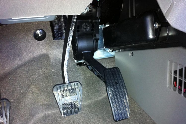
Электроника – штука надежная, но иногда она выходит из строя.
Устройство и принцип работы электронной педали газа
Чтобы понимать, как это устроено и функционирует, нужно примерно понимать общую схему механического аналога. Функции этих систем схожи, однако самым простым узлом можно считать только традиционный привод.
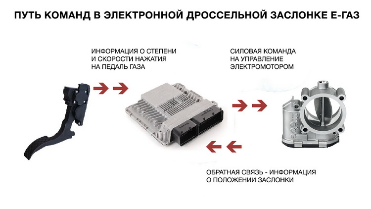
Педаль «газа» — это орган управления дросселем и его заслонкой. Функция дросселя – регуляция количества воздуха. Чем больше воздуха, с тем большими оборотами будет вращаться коленчатый вал двигателя. Педаль через тросиковый привод либо через рычаги соединяется с приводом дросселя. Все это значительно снижает усилие, необходимое для нажатия на газ.
Принцип действия электронного узла сложнее, но таким образом процесс управления оборотами стал легче. Электронный акселератор используется только на моторах с инжекторной системой питания. Устройство ее – полностью электронное. В основе лежат электронные модули, преобразующие электрические сигналы.
Конструктивно узел представляет собой рычаг из пластика и крепежный кронштейн – внутри кронштейна имеются два датчика. Все эти элементы составляют цельную неразборную конструкцию.
В качестве датчиков используются потенциометры. Подвижный контакт которых находится в жесткой связи с осью рычага пластиковой педали.
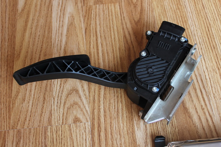
Когда водитель нажимает на акселератор, электроника отправляет блоку, отвечающему за преобразование сигналов, данные об положении рычага. На следующем шаге сигнал усиливается и дроссель открывается в соответствии с настройкам автомобиля.
Если рассмотреть классическую схему, то ось педали совмещается с ползунком потенциометра. Переменный резистор изготовлен на печатной плате по технологии напыления. При нажатии на акселератор ползунки потенциометра двигаются по напыленной поверхности, меняя сопротивление в цепи.
В новых моделях авто применяют два потенциометра. Данный подход увеличивает надежность и точность управления. При поломке одного резистора система будет использовать показания второго.
Признаки неисправности
Среди основных признаков проблем можно выделить:
- Отсутствие какой-либо реакции на акселератор после запуска ДВС автомобиля;
- Провалы, потеря приемистости в процессе движения;
- Плавающие холостые обороты;
- Резкие скачки оборотов при плавном нажатии на акселератор;
- Слишком высокие обороты в режиме холостого хода.
В устройстве имеются подвижные электрические контакты, а также токопроводящие дорожки – эти элементы подвергаются износу в процессе эксплуатации. В работе мотора можно наблюдать провалы при наборе оборотов, нестабильный холостой ход.
Если в узле имеется неисправность, то водитель может это увидеть по сигнальной лампе на приборной панели. ЭБУ в такой ситуации переведет двигатель в резервный режим работы.
В таком режиме можно наблюдать медленный набор оборотов, даже если нажать на акселератор резко. Кроме того, может существенно вырасти расход топлива автомобиля.
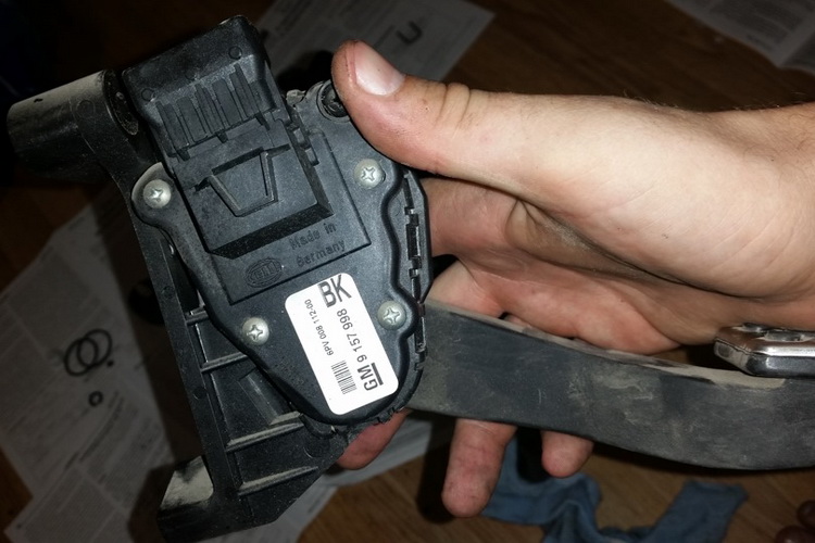
Если в узле выходят из строя сразу два датчика, ЭБУ переведет работу ДВС в аварийный режим – водитель не сможет влиять на работу мотора, обороты при любых условиях будут немного выше оборотов ХХ.
Проверка
Если в устройстве имеется потенциометры, то они проверяются обыкновенным мультиметром. Необходимо использовать электрическую схему конкретного автомобиля. Чтобы не пришлось снимать весь узел, контролировать сопротивление можно со стороны ЭБУ.
Для проверки понадобятся знания распиновки ЭБУ и уровень сопротивлений потенциометра в разных положениях педали.
Если педаль цифровая, тогда ее проверка возможна только при наличии систем компьютерной диагностики.
Регулировка
Процесс регулировки на разных моделях авто может различаться, так как разные производители используют механизмы разной конструкции. Но для настройки можно применять одинаковый принцип. Что касается конкретной модели, то лучше заранее найти информацию по нему.
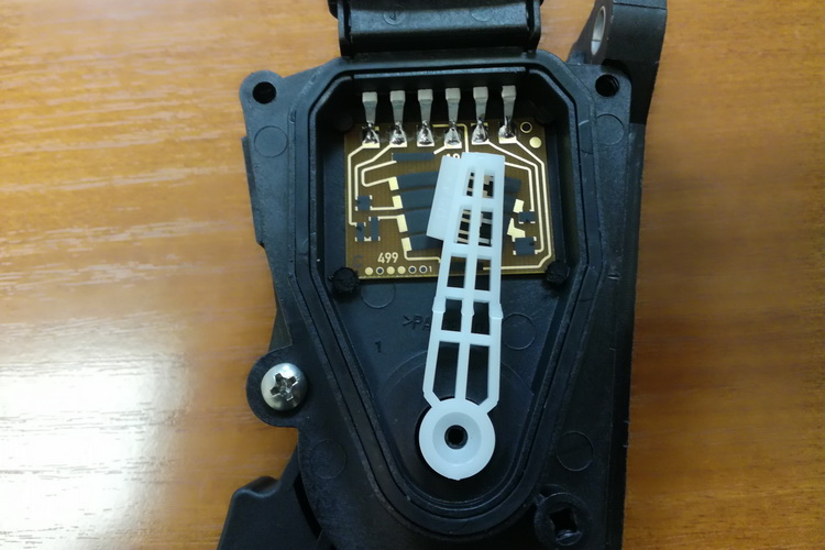
Для начала регулировки первым делом необходимо демонтировать педаль с удерживающего кронштейна. Далее ослабляют винты, крепящие крышку. Одни винт удерживает крышку в определенном положении – его следует выкрутить полностью. Крышку поворачивают в сторону по часовой стрелке до конца, затем снова затягивают винты.
Данная регулировка позволит сократить время реакции педали. Некоторые автовладельцы отмечают что после таких регулировок скорость срабатывания можно даже сравнивать с механической педалью. Регулировка позволяет улучшить работу мотора, улучшить начало движения с места.
В тех случаях, когда нужна педаль с низкой чувствительностью, необходимо вращать крышку в обратную сторону – против часовой стрелки. Машина начинает реагировать на нажатия не так быстро.
Иногда можно встретить и вредные советы по регулировке –водители советуют подкладывать прокладки под рычаг. Это неверный подход. Иногда подкладки попадают под контактные площадки в потенциометре, а машина в результате может потерять управление.
Ремонт
Если с педалью появились какие либо проблемы, тогда поможет только полная замена узла. Но прежде чем что-то менять, стоит выявить причину неисправности. Для этого можно воспользоваться проверкой с мультиметром.
Можно разъединить датчики и колодку, демонтировать педаль. Проверяют сопротивление – при нажатии на газ оно должно медленно меняться. Скачки показателей говорят о неисправностях.
Но иногда ремонт возможен – например, повреждена проводка. При обнаружения дефекта с проводкой можно использовать следующую схему.
ESTUN E300 Operation Manual
This document provides guides to use the E300 device for the jobs.
According to this document, you can learn how to program the product by the E300 device.Audience
This document is intended for:
Technical support engineer
Installation and Commissioning engineer
operating staffOrganization
Chapter Content Chapter 1 Outline This chapter describes the features, appearance, and electrical specification
of the E300 device.Chapter 2 Programming This chapter guides the user how to program the product by the E300 device. Chapter 3 Basic Operation This chapter describes the basic operation of the E300 device. Conventions
- Symbol Conventions
The symbols that may be found in this document are defined as follows.
- General Conventions
- GUI Conventions
- Keyboard Operation
Part1 — Outline
1.1 Introduction
- The E300 is a dedicated NC (numerical control) device for the Torsion Bending Machine, which combines the expertise of ESTUN for many years and provides a complete economic solution for the Torsion Bending Machine with the support of unique drive control technology.
- The E300 device adopts the integral product structure, built-in high-performance A8 processor, and configures 5.6 inch, 640 × 480 dot matrix, 18 full color display screen, and integrated IO ports, serialports and USB port.
- The E300 device is designed to be operated via the buttons on the front panel. At the same time, the pump switch and the emergency stop button are installed in the customized suspension cabinet tomeet the user’s requirements, as shown inFigure 1-1.
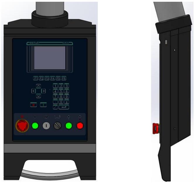
Figure 1-1 The suspension cabinet
1.2 Features
The E300 device inherits ESTUN classic mode of operation, through a simple and intuitive parameter configuration interface to complete the bending machine control operation. Its friendly
interface, easy to use, practical function, and has the following features: 4 axes are supported, viz, X-axis, Y-axis, R-axis and C-axis.
Automatic calculation of the block position, according to the bending angle, material, thickness and mold parameters.
The back gauge can be controlled in a high-accuracysince the servo systems control X-axis and R-axis.
Optional hydraulic or mechanical to control the C-axis.
Program in absolute value or angle.
You can backup, restore, import and export the parameters, for commissioning the machine easily.
Edit the program in one page, for improving the operating efficiency.
You can program the dwell time (holding time) andretracting delay by the device instead of the time relay.
Interference or collision of the die can be avoided.
The opening distance can be adjusted, for improving the operating efficiency.
Automatically adjust the clamping point position.
You can view the status of inputs, outputs, valves and faults on the Monitor page at any time.
Automatically adjust the zero position of the R-axis.
Materials and die informations are programable.
Three of operation mode (Jog, Single, Continuous) for the jobs.
Language setting and unit setting.
IO ports can be allocated freely, and the device can detect them for avoid the repeat.
Bilateral positioning and unilateral positioning.
Slug clearance function.
Teaching or search the reference point.
The Axis, which is controlled by a servo system, can be manually moved.
Real-time memory the parameters, positions and programs against the unexpectedaccidents such as interruption of power supply.1.3 Appearance
- Control Panel
Figure 1-2 is the appearance of the suspended device, and it includes many elements.
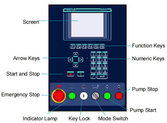
Figure 1-2 Appearance of the suspended device
Table 1-1 lists the description of each element.
Table 1-1 Description of each element
- Ports
There are 6 kinds of ports on the E300 device, which can connect the external devices. Table 1-2lists the description of them.
Table 1-2 The description of Ports
Port Diagram Amount Description USB / 1 Connect a U disk, which can help the USB - 1 user by performingmany operations
such as update, import or export the
parameters, dies and programs.DB-9
(Male)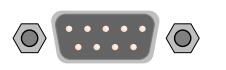
1 Reserved. IO 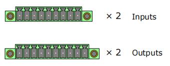
4 2 groups of inputs, each group have 9 pins.
2 groups of outputs, each group have 10 pins.RJ45 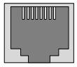
1 Connect the servo system by CAN
protocol.DB-15
(Female)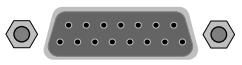
1 Connect the external device, which
controls C-axis.DB-9
(Female)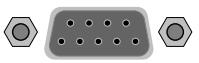
2 Reserved. 1.4 Electrical Specifications
Power Supply Item Voltage Rated Current Starting Current Minimum 20 1.2 / Standard 24 2 / Maximum 28.8 3 3 Unit V A A Inputs Input Voltage 24VDC±10% Input Current 5mA Signal Characteristic H-level is not greater than 30V
L-level is not greater than 1.2VEffective Level H-level Outputs Output structure Open Collector Output Voltage Not greater than 30VDC Output Current Not greater than 150mA Signal Characteristic H-level is not greater than 30V
L-level is not greater than 1.0VEffective Level L-level Encoder Supported Type Differential / Line Driver Complementally / Voltage Supply Voltage 5V DC 12V DC Supply Current 500mA Response Frequency 500KHz Input Phases A, B, C, A\, B\, C\ Output Phases A, A\, B, B\, C, C\ A, B, C Output Voltage H-level is not less than 80%VCC
L-level is not greater than 0.3VCommunication Protocol CAN RS485 RS232 Transmission Rate 1 Mbps 10 Mbps 115.2 Kbps Terminal Resistance Build-in None ESD 16KV HBM 15KV HBM Analog Input Type Voltage Range From ﹣10V to ﹢10V Resolution 12bit Channels 3 channels Sampling Frequency Not greater than 78KHz Analog Output Type Voltage Range From ﹣10V to ﹢10V Resolution 12bit Channels 2 channels (AO1 to AO4) Environment Operating TMP 0℃ to 40℃ Operating Humidity 5% to 95%, no condensation Storage TMP ﹣20℃ to 70℃ Storage Humidity 5% to 95%, no condensation Part2 — Programming
2.1 Page Structure
Power up the device and wait for a while, the screen can display the initialpage (Single-Step) automatically, as shown in Figure 2-1
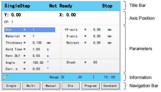
Figure 2-1 The initial page
- Title Bar
This area is displayed on every page, and from left to right are Page Name, System Status, and Operation Mode in turn.
Page Name: displayed the current page’s name, e.g. SIngleStep, Multi, Program.
System Status: displayed the current system status. There are six system statuses, as shown in Table 2-1.Table 2-1 The description of the system status
System Status Description Not Ready When power up the device, the system detects the signalPump is turned OFF, this system status is displayed. Idle When this system status is displayed, the signal Pump is turned ON, and the signal RDY is also turned ON.
Only under this system status, the machine can run the programming after you has completed the program and press down the START key.Run When the system is working, this status is displayed.
When you press STOP key on the operation panel, the machine stops and the system status is switched to Idle.
If the Count Mode is set to Cnt Down, when the counting has been finished,(Stock is 0), the machine stops and the system status is switched to Idle.
When any problem doesn’t meet the device settings or prevents normal operation is detected,the machines stops and the system status is switched to Alarm.Alarm When any problem doesn’t meet the device settings or prevents normal operation is detected, the status is displayed.
Follow the section Appendix D Alarm List, solving the fault according to the fault message, and then move the cursor on Clear, and press ENTER key, so that the system can try to reset. Operation Mode: displayed the current operation mode. There are three operation modes, as shown in Table 2-2.
Table 2-2 The description of the operation mode
- Axis Position
This area displays the current position value of the axes.
Note: In general, the default issued E300 device is the standard version, which only supports the control of X-axis and Y-axis. For the more features, you can contact ESTUN.
- Parameters
This area displays the parameters information. Each page has corresponding parameters, for details about the parameters see the description of the other sections in this manual.
- Information
This area displays the information of each parameter, including editing value and range. The right side of this area is the system time.
- Navigation Bar
This area displayed each main page you may be switched, corresponding to the F1 to F6 keys on the operation panel.
Table 2-3lists the descriptions of each main page.
Table 2-3 The descriptions of each main page
Key Page Description F1 Single This page is used for setting the parameters of the single-step programming.
Single-step programming is commonly employed for quick bending.F2 Multi This page is used for setting the parameters of the Multi-step programming.
Multi-step programming is commonly employed for the complex bending, which consist
of many different bending steps.F3 Manual The servo axes, which are controlled by servo motor, can be moved manually with the
arrow keys in this page. You can perform this operation without starting the device.F4 Die This page lists the information of the set and stored dies. F5 Programe This page lists the information of the set and stored programs. F6 Constant The commonly used parameters are displayed on Constant page. 2.2 Operation Flow
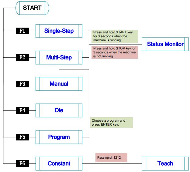
Figure 2-2 Operation flow diagram
2.3 Single-Step
- Description
You can program the bending steps for the same settings on this page, which is commonly employed for quick bending.
This page is the initial page when you power up the device. Press F1 key to enter the Single-Step page, as shown in Figure 2-3.
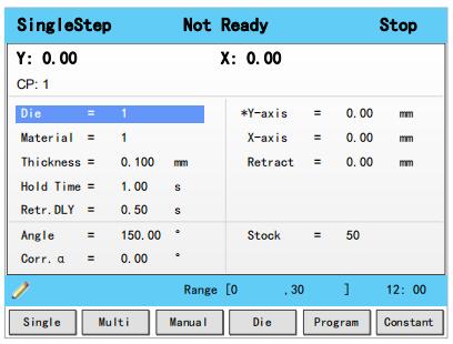
Figure 2-3 The Single-Step page
Table 2-4 lists the description of the parameter on this page. You can refer to this table when you edit the parameters on this page.
Table 2-4 The description of the parameter on Single-Step page
- Example
We take the following process as an example to describe the programming.
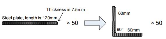
Steel plate, length is 120mm 60mm 90° 60mm Thickness is 7.5mm × 50 × 50.
In this example, we can learn a set of the basic data: material is steel; X-axis is 60; bending-angle is 90; thickness is 7.5; stock is 50.
We decide to program the process by the given angle, and supposing the die ID is 1.
In addition, we can set some other necessary parameters according to our experience, such as holding time is 3, retracting delay is 2, and retract distance is 5.Follow the below procedure to perform the program.
1. Move the cursor on Die, and type 1.
Note: For details about the setting of the die, see the section 2.6 Die Settings.
2. Move the cursor on Material, and type 1.
3. Move the cursor on Thickness, and type 7.5.
4. Move the cursor on Hold Time, and type 3.
5. Move the cursor on Retr. DLY, and type 2.
6. Move the cursor on X-axis, and type 60.
7. Move the cursor on Retract, and type 5.
8. Move the cursor on Angle, and type90.
9. Move the cursor on Stock, and type 50.
Note: please set the Count Mode to Cnt Down on the Constant page beforehand.
10. Press START key on the operation panel.
Now, the servo-axis can start to positioning. When the machine is ready, it can be produced.2.4 Multi-Step
- Description
You can program the bending steps for the different settings on this page. Multi-step programming is commonly employed for the complex bending, which consist of many different bending steps.
Press F2 key to enter the Multi-Step page, as shown in Figure 2-4.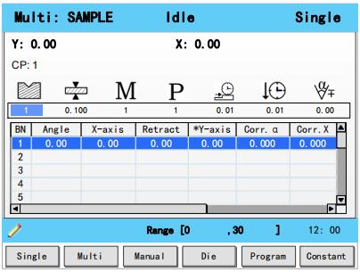
Figure 2-4 The Multi-Step page
Table 2-5lists the description of the parameter on this page. You can refer to this table when you edit the parameters on this page.
Table 2-5 The description of the parameter on Multi-Step page
Parameter Description 
Default 1
Range 0 to 30
Unit - Description Set a desired die ID for the program. The parameters of the die can be edited on Die page.
Default 0
Range 0.000 to 99.999
Unit mm
Description The thickness of the sheet.
Default 1
Range 1 to 6
Unit - Description Set a desired material ID for the program, which is used for calculating the
bending depth. The parameters of the material can be edited on Material
Table page.
Default 0
Range -1 to 999 999
Unit - Description The stock counter is incremented or decremented after each end of a program cycle, which depends on the settings of the parameter Count Mode.
Set it to -1, indicating the stock count is disabled.
Set it to other value:
When the Count Mode is Cnt Down, the stock counter in production mode is
decreased by 1 after each product cycle. When the counter has reached 0, the
machine is stopped.
When the Count Mode is Cnt Up, the stock counter in production mode is
increased by 1 after each product cycle.Parameter Description 
Default 0
Range 0.00 to 99.99
Unit s
Description The wait time before the X-axis performs the retract.
Default 0
Range 0.00 to 99.99
Unit s
Description The hold (dwell) timeof punch at the bending point.
Default 0
Range -90.00 to 90.00
Unit °
Description This parameter is valid when the bending method is angle, which indicates the correction on angle to the whole bending. For example:
If the programmed value is 90, while the actual measured value is 92, then
this parameter shall be set to -2.
If the programmed value is 90, while the actual measured value is 88, then
this parameter shall be set to 2.BN Default 1
Range 1 to 25
Unit -
Description This parameter indicates the current bending step in the program.Angle Default 0
Range 0.00 to 180.00
Unit °
Description Set a desired angle value in the selected bending step.X-axis Default 0
Range 0.000 to 9 999.999
Unit mm
Description The programmed value for the X-axis.Retract Default 0
Range 0.000 to 9 999.999
Unit mm
Description Retract distance of the selected axis in the current bend. The «backgauge
retract» is started when the beam is pinching the sheet.Open Default 0
Range 0.00 to 99.99 or 0.000 to 9 999.999
Unit s or mm
Description Set the opening distance or opening time for the opening process.Y-axis Default 0
Range 0.000 to 9 999.999
Unit mm
Description The programmed value for the Y-axis.- Example
We take the following process as an example to describe the programming.

In this example, there are 2 bending steps, and we can learn a set of the basic data: material is steel; one X-axis is 30 and other is 120; bending-angle is 90; thickness is 7.5; stock is 50.
We decide to program the process by the given angle, and supposing the die ID is 1.
In addition, we can set some other necessary parameters according to our experience, such as holding time is 3, retracting delay is 2, and retract distance is 5.
Follow the below procedure to perform the program.2. Move the cursor on
(Die), and type 1.Note: For details about the setting of the die, see the section 2.6 Die Settings.
3. Move the cursor on
(Thickness), and type 7.5.
4. Move the cursor on(Material), and type 1.
5. Move the cursor on(Stock), and type 5.
6. Move the cursor on(Retr. DLY), and type 2.
7. Move the cursor on(Hold Time), and type 3.
8. Move the cursor on Angle where BN is 1, and type 90.
9. Move the cursor on X-axis where BN is 1, and type 30.
10. Move the cursor on Retract where BN is 1, and type 5.
11. Move the cursor on BN, and press ENTER key.
Then, press OK on the pop-up dialog-box to create a new bending step.
12. Then, press OK on the pop-up dialog-box to create a new bending step.
13. Move the cursor on X-axis where BN is 2, and type 120.
14. Move the cursor on Retract where BN is 2, and type 5.
15. Press START key on the operation panel.Now, the servo-axis can start to positioning. When the machine is ready, it can be produced.
2.5 Manual Movement
The servo axes, which are controlled by servo motor, can be moved manually with the arrow keys in
Manual page. You can perform this operation without starting the device.
Perform this operation can help you adjust or commission the machine.
To enter the Manual page, power up the device and wait for the device displays the default page, and then press F3 key, as shown in Figure 2-5.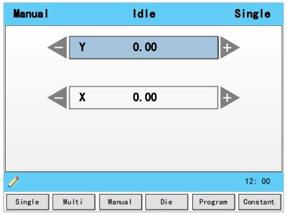
Figure 2-5 The Manual page
Press the arrow keys UP and DOWN to select the desired servo-axis.
Press the arrow keys LEFT and RIGHT to select proper movement direction.2.6 Die Settings
To program the process by the given angle, it is necessary to set parameters of the die.
Press F4 key to enter the Die page, as shown in Figure 2-6.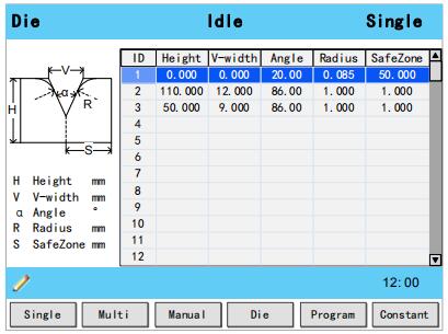
Figure 2-6 The Die page
Press arrow keys UP and DOWN to select the desired die ID.
Press arrow keys LEFTand RIGHT to select the desired parameter of the die.
Press NUMERICkeys to type the proper value.The technical parameters diagram of the die are as shown in Figure 2-7.
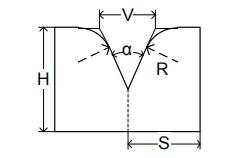
Figure 2-7 The technical parameters diagram of the die
H: The height of the die, which is used in the bend depth calculation.
V: The length of V-opening, which is the distance between the touching lines crossing.
α : The angle of the die.
R: The radius of the edges of the V-opening.
S: Safety distance, which will be used in the case an R-axis,is mounted. This to prevent finger to die collision. The indicated minimum value iscomputed automatically from the die dimensions as follows:
S = FS+V/2, in which:
FS = flat section on the back side of the V-grove
V = opening value.2.7 Bend Correction
It is necessary to commission the machine before your actual processing, in order to win an accurate bending result.
For performing it, you can program a bending process on Single-Step page, and operate the machine to complete one processing.
Then, measure the actual bending angle, bending depth, and the distance of the back gauge.
Check whether the bending result is corresponding with your requirement.- Angle correction
The range of this parameter is from -90 to 90.
When the actual axis position is not corresponding with the displayed value, it is possible to correct the position with this parameter.For example:
When the programmed and displayed value is 90, while the actual axis positionvalue is 92, then you shall set the Corr. α to -2.
When the programmed and displayed value is 90, while the actual axis positionvalue is 88, then you shall set the Corr. α to 2.- Y-axis correction
The range of this parameter is from ﹣99.999 to 99.999.
When the actual axis position is not corresponding with the displayed value, it is possible to correct the position with this parameter.
It may be repeating to set Corr. Y. However, we can learn from experience, program the process by the given angle, and measure the depth of 1 degree as the unit length. Then, program the process by the given depth, and set Corr. Y according to the unit length. Repeat this operation, until the bending result is corresponding with your requirement.- X-axis correction
The range of this parameter is from ﹣99.999 to 99.999.
When the actual axis position is not corresponding with the displayed value, it is possible to correct the position with this parameter.The setting of X-axis correction is same with Angle correction. For example:
When the programmed and displayed value is 100.00, while the actual axis position value is 102.05, then you shall set the Corr. X to -2.05.
When the programmed and displayed value is 100.00, while the actual axis position value is 98.05, then you shall set the Corr. X to 1.95.Note: The machine can stop any time in Single-Step bending, and then you can modify the programmed value of X-axis, so Corr. X is not necessary in Single-Step programming. However, there are a number of bending steps in Multi-Step programming, and Corr. X is assigned to each step.
2.8 Program Management
2.8.1 Create a Program
Press F5 key to enter the Program page, as shown in Figure 2-8.
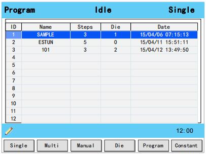
Figure 2-8 The Program page
Move the cursor on the program Name, and press NUMBERS keys to type a desired name. The typing method is 10 keys, that is, the numbers and letters on the same key can be switched by
pressing severaltimes. For example, 2, C and D are in the same key, press once, shown as 2; quickly press twice, shown as C; quickly press three times, shown as D.
Press ENTER key to confirm your typing, the software can generate the Steps, Die and Date.2.8.2 Edit the Program
Move the cursor on the program ID you want to edit, and press ENTER key to enter the Multi-Step page. In addition, when you enter the Multi-Step page, the selected program has been loaded.
For details about the program see the section 2.4 Multi-Step.2.8.3 Delete a Program
Move the cursor on the program ID you want to delete, and press CLEAR key. The page can display a dialog for asking whether to delete the selected item. Press OK to delete the selected program.
2.9 Teaching
In order to obtain the position values of the servo axes, the user needs to perform Teaching operation before the bending process, which can indicate the current position of the servo axis.
The diagram of machine coordinate system is as shown in Figure 2-9. You can refer to this diagram to complete the teaching value of the measurement and set.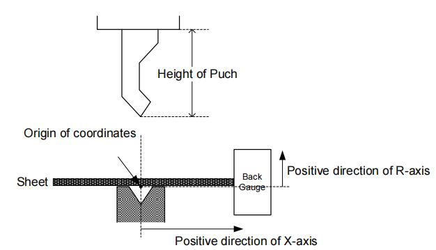
Figure 2-9 Coordinate systemof machine
Type the password 1212 in Constant page to enter TechIn Para page, as shown in Figure 2-10.
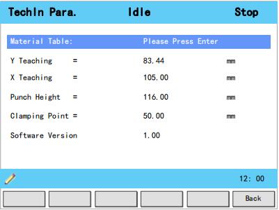
Figure 2-10 TechIn Para page
Press the arrow keys UP and DOWN to select a parameter, and type the desired value for them.
- Y Teaching and Clamping Point
The purpose of teaching Y-axis is obtaining the comparativeposition value of clamping point. When you teach Y-axis, it is necessary to estimate the position value of the Y-axis in advance. For example, if the position of the Y-axis is estimated to be 50mm, and the procedureis as follows:
Step 2 Select the parameter Y Teaching in TechIn Para page, and set it to 50.
Step 3 Return to the Single-Step page, and set the parameter Angle to 180, and the other parameters can be set arbitrarily.
In general, when the machine is in clamping, the punch just against the top of the sheet, so the bending Angle is set to 180, in order to ensure that the sheet was clamped.
Step 4 Run the device, and record the Y-axis position displayed on the device when the process is in Dwell.
Step 5 Enter the TechIn Parapage again, and fill the recorded value in the parameter Clamping Point.Note: The relationbetween Y Teaching and Clamping Point is comparative. If the position of Y-axis has been changed, you must perform the above procedure for obtaining the value of Clamping
Point again.- X Teaching
To teach the X-axis, you can measure the actual position of the X-axis, that is to say, measure the linear distance between the V-opening center of the die and back gauge.
Although there are many methods for teaching X-axis, their purpose is to ensure the processing accuracy. It is recommended that the user can run the machine once after roughly measuring the
distance, that is, program a simple Single-Step program. For example, the measurement of the X-axis distance of 100mm, and the procedureis as follows:
Step 6 Select the parameter X Teaching in TechIn Parapage, and set it to 100.
Step 7 Return to the Single-Step page, and set the parameter X-axis to 100, and the other parameters can be set arbitrarily. Here we need not to consider the error from the machine itself.
Step 8 Run the machine. When the bending step has been completed, measure and record the worked sheet.
Step 9 Enter the TechIn Para page again, and fill the recorded value in the parameter X Teaching.Note: It is necessary to perform the above procedures for several times for ensuring the accuracy of the working.
- R Teaching
To teach the R-axis, you can measure and record the actual position of the R-axis directly, that is, measure the vertical distance between the top of the die and the back gauge. Then, enter the TechIn Para page again, and fill the recorded value in the parameter R Teaching.
Part3 — Basic Operation
3.1 Start
- How to start
Press START key to startup the machine when you complete the program on Single-Step page or Multi-Step page, the servo-axis can start to positioning. When the machine is ready, it can be
produced.However, it is unavailable to press START key on other pages.
- Start state
When the device is running, its indicator lamp can be lighting. In addition, you can see the status on the top of page is RUN.
3.2 Stop
- How to stop
There are 3 cases for stopping the device.
Stop by a fault: If any fault occurred during the operation, the machine can stop automatically. Normally Stop: it also includes the following case:
Manual stop: press STOP key, the running machine can stop.
Count is finished: for the Count Mode is Cnt Down, when the Stock is 0, the running machine can stop automatically.
Emergency Stop: press down EMERGENCY STOP button, the power supply of the system can be cut off.- Stop state
When the device is stopped, its indicator lamp can be lighting. In addition, you can see the status on the top of page is Idle or Alarm.
3.3 Alarm and Reset
- Alarm information
As shown in Figure 3-1, which indicates a fault had occurred during the operation. It is necessary to solveit for recovering the running machine.
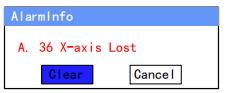
Figure 3-1 An alarm information occurred
- How to reset
Follow the section Appendix D Alarm List, solving the fault according to the fault message, and then move the cursor on Clear, and press ENTER key, so that the system can try to reset.
However, the fault message may display again if the fault hasn’t been solved properly.
Move the cursor on Cancel and press ENTER key, the AlarmInfo dialog-box can be hiddentemporarily. To display it again, press CLEAR key when the page is on SingleStep or Multi-Step.3.4 Monitor
You can view the ports allocation, valve status and fault list on Status Monitor page.
Press and hold STARTkey for 3 seconds when the machine is running.
Press and hold STOP key for 3 seconds when the machine is not running.- Valve state
When you enter Status Monitor page, you can view the Valve Status tab, as shown in Figure 3-2

Figure 3-2 Valve status monitored
On Valve Status tab, you can view the output status of valves. Blue background />indicates the port is turned ON while Blank indicates the port is turned OFF.
You can view the current valve status on Curr.row, and the other rows shows the allocation in corresponding process.
For example, you have allocated the process Press as YV1 and YV3, when the machine is in Press process, the Curr.Row displays />on YV1 and YV3.- I/O state
Press arrow key RIGHT on the Valve Status tab, you can view the IO Status table, as shown in Figure 3-3.
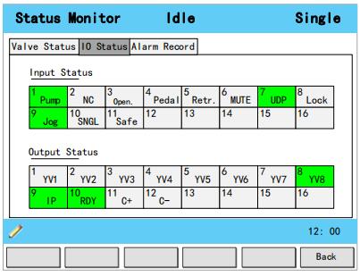
Figure 3-3 IO status monitored
Green background
 indicates the port is turned ON, while Blank indicates the port is turned OFF.
- Alarm history
Press arrow key RIGHT on the IO Status tab, you can view the Alarm Record table, as shown in Figure 3-4.

Figure 3-4 Alarm history page
ID: numbering for the alarm list, descending sort by Alarm Date, i.e. ID 1 is the latestfault message.
Alarm Num: to show the code of the fault. For detail about solving the faults, see the section.Appendix D Alarm List.
Alarm Reason: to show summary recordof the fault.
Alarm Date: to show when this fault occurred.3.5 Constant
The commonly used parameters are displayed on Constant page, as shown inFigure 3-5.
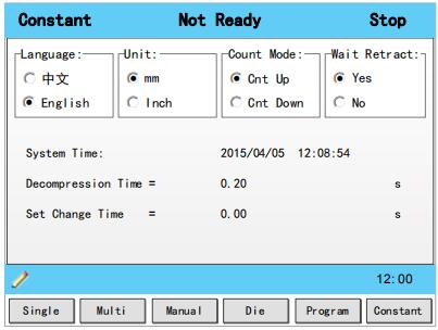
Figure 3-5 The Constant page
Table 3-1 list these parameters and their description.
Table 3-1 The description of the parameters onConstant page
Parameter Description Language Select a desired language for the pages. Unit Select a desired length scale for the dimensions.
E300 can convert the current dimensions automatically when you change this parameter.Count Mode Select a desired stock count mode.
To select Cnt Up, the stock counter in production mode is increased by 1 after each
product cycle.
To select Cnt Down, the stock counter in production mode is decreased by 1 after each
product cycle. When the counter has reached 0, the control is stopped.
Down counting can be useful if a pre-planned quota must be produced. Up counting could
be used to give a report on production progress.Wait Retract In the case of a retract, let the Y-axis wait until the retract is finished.
To select Yes, when the Y-axis reaches the clamping point, the Y-axis is stopped and the
retract is started. When the retract is completed, the Y-axis moves on.
To select No, the retract is started when the Y-axis passes the clamping point, the Y-axis
does not stop.System Time Set to a proper time for the system. The format is yyyy/MM/ddHH:mm:ss.
For example, 2015/11/23 14:51:00.Decompression Time Set the durationfor the decompression process. This parameter affects the time for tuning ON the valve of Decmp. Set Change Time Set a waiting time for entering next step when the previous step is completed. Intermediate R Temporary position for the R-axis, to avoid collision as a result of movement of the X-axis.
The value 0 disables this functionality. When programmed not equal to zero thisposition will
be active when the X-axis has to move inside the safety zone of the die.
The sequence will be as follows:
a. The R-axis is moved to the intermediate position;
b. then the X-axis is moved to its intended position;
c. finally the R-axis is moved to its intended position.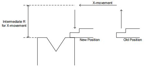
Appendix A Glossary
Glossary Description Axis A reference direction, which can make the parts of the machine do the linear motion or rotation
motion.Machine Coordinate System Cartesian coordinate system based on machine zero, which is fixed on the machine. Computerized Numerical
Control, CNCFulfill the numerical control the processing functions by the computer. Reference Position A fixed point along the axis, which can be referenced to the origin of the machine. Hardware Limit A limit position, which is mounted in the machine, can limit the movement of the parts. Software Limit A limit range, which is programmed in the device, can limit the movement of the parts. Mute A position where the process switches from Fast-Closing to Pressing. DA (Digital to Analog) To convert the Digital signal into the Analog signal. In general, decode the digital signal and convert into a corresponding level, which can form a step shape signal, and then perform a low-pass filtering. AD (Analog to Digital) To convert the Analog signal into the Digital signal. The analog signal is subjected to a line filter, and then samples the hold circuit to be a step shapesignal, and then the step shape signal is converted into a binary code by the encoder, that is, the desired digital signal. UpperDead Point, UDP The critical position for the movement of the beam, where the beam cannot continue to move
upwards.Punch Also known as male mold, which is a die part forming the shape of the end face. Die Also known as female mold, which is a die part forming the shape of the outer. Lower Dead Point, LDP The critical position for the movement of the beam, where the beam cannot continue to move downwards.The theoretical position is at the lowest point of the V-Opening. Fast Closing One process of the bending step, which can make the beam moves to Mute fast. Pressing One process of the bending step, which can make the beam moves from Mute to bending point. Dwell In order to ensure the formation of the workpiece, it is necessary to keep the pressure for a period of time when the punch has been reached the bending point, against the tensile strength of the material. Appendix B Parameters Lists
The double asterisk (**) at the front of the parameter indicates this parameter is displayed when you have updated the function.
- Constant
- Material Table
- TechIn Para
- Program
Default 0
Range -90.00 to 90.00
Unit °
Description This parameter is valid when the bending method is angle, which indicates the
correction on angle to the whole bending. For example:
If the programmed value is 90, while the actual measured value is 92, then this parameter shall be set to -2.
If the programmed value is 90, while the actual measured value is 88, then this parameter shall be set to 2.Steps Default 1
Range 1 to 25
Unit -
Description This parameter displays how many steps in the selected program.BN Default 1
Range 1 to 25
Unit -
Description This parameter indicates the current bending step in the program.X-axis Default 0
Range 0.000 to 9 999.999
Unit mm
Description The programmed value for the X-axisY-axis Default 0
Range 0.000 to 9 999.999
Unit mm
Description The programmed value for the Y-axis.**
R-axisDefault 0
Range 0.000 to 9 999.999
Unit mm
Description The programmed value for the R-axis.**
C-axisDefault 0
Range 0.000 to 9 999.999
Unit mm
Description The programmed value for the C-axis.Retract Default 0
Range 0.000 to 9 999.999
Unit mm
Description Retract distance of the selected axis in the current bend. The «backgauge
retract» is started when the beam is pinching the sheet.Appendix C Timing Charts
As shownFigure C-1andFigure C-2, you can view two timing charts, which are taken one ordinary bending step as the examples for representing the working status of each component.
Снятие и установка педали управления дроссельной заслонкой
Педаль управления дроссельной заслонкой снимают для замены при выходе из строя, так как она представляет собой не подлежащий ремонту узел и поставляется в запасные части только в сборе.
1. Отсоедините провод от клеммы «минус» аккумуляторной батареи.
ПРИМЕЧАНИЕ: Рулевая колонка снята для наглядности фотосъемки.

3. Выдвиньте стопор колодки жгута проводов датчика положения педали управления дроссельной заслонкой.

4. . сожмите фиксатор и отсоедините колодку от педали.

5. Выверните болт крепления педали управления дроссельной заслонкой к кронштейну педального узла.

6. . и снимите педаль.

7. Установите педаль управления дроссельной заслонкой в порядке, обратном снятию.